
Summary

- Plugin name : Connectivity Measure
- Version : 1.0
- Author : Alison Cellard
- Company : Inria
- Short description : Measure connectivity between pairs of channel
- Documentation template generation date : Dec 3 2018
Description
Measure connectivity between pairs of channel using the kind of measure chosen (PLV, MSC, etc.)
This box measure connectivity between pairs of channels using several method. For now, Single-Trial Phase Locking Value [1] is available.
The coherence definition used is :
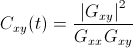
With Gxy the cross-spectral density between the two input signal channel, and Gxx and Gyy the auto-spectral densities, respectively for the first and second channels of the pair. The spectral densities are estimated via Welch's method [2]
[1] JP Lachaux, E Rodriguez, M Le Van Quyen, A Lutz, J Martinerie, FJ Varela, Studying single-trials of phase synchronous activity in the brain, International Journal of Bifurcation and Chaos in Applied Sciences and Engineering vol.10 p.2429-2440, 2000. [2] Welch, P.D. (1967) "The Use of Fast Fourier Transform for the Estimation of Power Spectra: A Method Based on Time Averaging Over Short, Modified Periodograms", IEEE Transactions on Audio Electroacoustics, AU-15, 70–73
Inputs
1. Input Signal
The input signal on which connectivity between channels needs to be measured.
- Type identifier : Signal (0x5ba36127, 0x195feae1)
Outputs
The number of outputs of this box can vary depending on the algorithm chosen. If you change the algorithm, the number of outputs can change, for this to be apply, you need to press apply, and close the box settings window.
If you choose the Magnitude Square Coherence, the box will have two outputs :
-
Mean Coherence signal
The mean value of coherence over all the frequencies found in the input signal at each time.
Typeidentifier : Signal (0x5ba36127, 0x195feae1)
-
Coherence spectrum
The coherence value at each frequencies.
Typeidentifier : Spectrum (0x1f261c0a, 0x593bf6bd)
As the default algorithm is Single-trial Phase-Locking value, the box has initially one input.
1. S-PLV signal
Default connectivity measure (S-PLV) between chosen channels
- Type identifier : Signal (0x5ba36127, 0x195feae1)
Settings
As for the outputs, the settings change according to the algorithm chosen. This documentation display only the three settings common to all algorithms. For more settings see Example description section.
1. Method
Choice of the algorithm to measure connectivity (PLV, coherence, etc.)
- Type identifier : Connectivity measure method (0xdc90c94b, 0xf82ad423)
- Default value : [ Single-Trial Phase Locking Value ]
2. Pairs of channels
A semicolon separated list of pairs of channel identifiers. Channels within a pair must be separated by a hyphen. You can use the index of the channel or the name of the channel. Also, ranges can be selected specifying first channel identifier, followed by a colon, followed by the second channel identifier. To select all channels at once, use '*'.
- Type identifier : String (0x79a9edeb, 0x245d83fc)
- Default value : [ 1-2 ]
3. Channel Matching Method
The kind of identification for channel list.
Smartlet the box try to detect if the channel identifier is an index or a nameNameforces the channel identifiers to be considered as channel names. This can be useful if channel names are numbers.Indexforces the channel identifiers to be considered as channel indices. This can be useful if channel names are numbers.- Type identifier : Match method (0x666f25e9, 0x3e5738d6)
- Default value : [ Smart ]
Examples
To use the Magnitude Squared Coherence you need to specify a few more settings due to the Welch's method which is to divide input dataset in several segments with a certain overlap and apply a window.

-
Window method
The window applied to segments when estimating spectral density
Defaultvalue [Welch]
-
Overlap
Define the overlap. The value is in percentage so it must be between 0 (no overlap) and 100.
Typeidentifier : Integer (0x007deef9, 0x2f3e95c6)Defaultvalue : [ 50 ]
-
Length of segments
Define the length of segment (in sample) in which the input signal will be divided. Be careful, by default, the data chunk in OpenViBE contain 32 samples, if you want to divide the chunks in segments longer than 32, you need to use the Time Based Epoching box to have longer chunks.
Typeidentifier : Integer (0x007deef9, 0x2f3e95c6)Defaultvalue : [ 32 ]
Miscellaneous
By default the box have one input for a signal set and you can measure connectivity between its channels. If you want to measure connectivity between two channels from two differents signals set, you can add an input. Please make sure the the two signal set have the same properties (same length, same sampling frequency). Also, note that in case of two input, the first channel of each pairs will be from the first input and the second channel from the second input.
Channel selection examples:
Single channel selection : 4-5
6-7, measure connectivity between channel 4 and 5 and between channel 6 and 7, if 2 inputs, this will measure connectivity between the 1st channel of input signal 1 and the 5th channel of input 2. Same goes for channel 6 and 7. Range selection : 1:4-5, measure connectivity between 4 pairs, equivalent to 1-5 2-5 3-5 4-5. All selection : 5-* measure connectivity between channel 5 and all the others or *-*, that form n*n pairs if one input signal with n channels or n*m pairs if two input signals with respectively n and m channels.
Generated on Tue Jun 26 2012 15:25:54 for Documentation by
 1.7.4
1.7.4