Box Processing & Signal Lables

Concerning processing components: filters, file load/save, visualizations, communication ...
Post Reply
amitpbarde
Posts: 7
Joined: Wed Sep 12, 2018 4:56 am

Box Processing & Signal Lables

Post by amitpbarde »

EDIT
I've used a Spatial Filter to get a single output going through to Unity using the LSL Export box. Is this a the right way to whittle down the number of signals using processing?

Hi,

I've been trying to design a scenario based on some ratios/formulas I've come across in McMahan, T., Parberry, I., & Parsons, T. D. (2015, June). Evaluating Electroencephalography Engagement Indices During Video Game Play. In FDG..

For the scenario given below, I've attempted to implement one of the Engagement Indices listed in the paper - Engagement = Theta/Alpha. The theta consist of Average frontal midline theta and the Alpha is the calculated average for the parietal region. Given that the Muse headband I'm using has only 4 electrodes - namely AF7, AF8, TP9 and TP10 - I've used AF7 and AF8 to obtain an average theta value and the TP9 and TP10 electrodes to obtain the average alpha value in the parietal region. These averages are then dived to obtain the "engagement" via a the Simple DSP box. I have the final output running into Unity via an LSL stream. From the image you will see that I have selected TP9 and TP10 to filter out the Alpha band and similarly AF7 and AF8 to obtain the Theta band. I'm using all the channels of the Muse Headband as Inputs for the EOG Denoising Input. I realise the box documentation says that the number of channels for both the inputs needs to be the same. This is a very dirty implementation of the ratios in literature, but I'm simply trying to figure out how openVibe works.
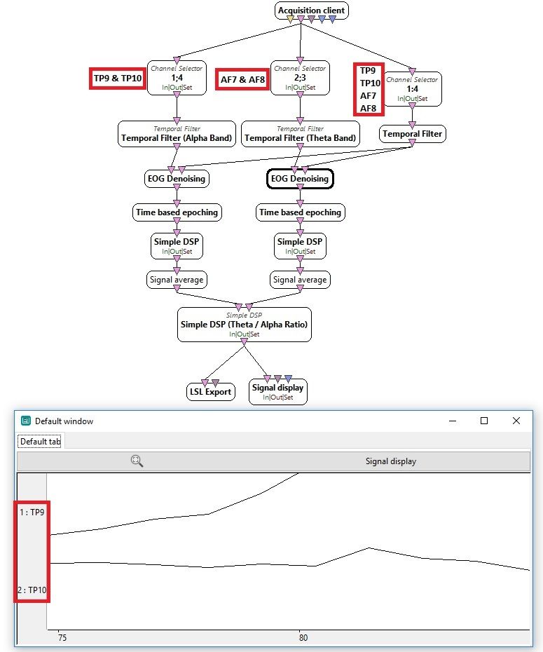
Image
Based on the screenshot above I have a few questions regarding the output:

1. Is there documentation with regards to how the boxes process the signals? While the current documentation provides some information, there is nothing to indicate what is going on. I'm asking because, the availability of some basic information may make it easier to understand the final output.

2. As you can see from the image, the final output displays the TP9 and TP10 electrode outputs, or so it seems at least. Is there an explanation for how the signal is being processed so as to obtain signals from only those two electrodes as the output? Or is the naming of the signals in the Y-axis of no consequence when the signal display box is used to view a processed output? Or could this be a result of not matching the channel counts for the EOG Denoising box?

3. Initially, I had only a single output controlling the graphic in Unity, but then realised that there were two outputs. For the time being I am simply dividing TP9 by TP10 inside my Unity script to make it look and behave in a manner that looks good. I suspect this is most definitely not the way to go about it, it want to display a real-time "Attention" or "Engagement" index.

Some explanation regarding processing in the signal chain and means to implement what I'm trying will be appreciated. I assume there's something within the openVibe Designer I'm missing that will allow me to send single value out of openVibe to Unity post processing.

Thanks,

Amit.

jtlindgren
Posts: 775
Joined: Tue Dec 04, 2012 3:53 pm
Location: INRIA Rennes, FRANCE

Re: Box Processing & Signal Lables

Post by jtlindgren »

Hi Amit, thank you for posting this description of what you are trying, it definitely can give ideas to people interested to do something 'neurofeedback-like' with OpenViBE.

Regarding your questions,
1. Is there documentation with regards to how the boxes process the signals? While the current documentation provides some information, there is nothing to indicate what is going on. I'm asking because, the availability of some basic information may make it easier to understand the final output.
For boxes its pretty much the box documentation and the tutorials. Each of them can reveal something of interest. The box documentation should be imo more complete than it currently is, but its always a matter of someone writing it, often based on investigating code already written a long time ago and the literature. It takes some effort. In any case, the docs can be found from

http://openvibe.inria.fr/documentation/ ... ithms.html
http://openvibe.inria.fr/documentation-index/
2. As you can see from the image, the final output displays the TP9 and TP10 electrode outputs, or so it seems at least. Is there an explanation for how the signal is being processed so as to obtain signals from only those two electrodes as the output? Or is the naming of the signals in the Y-axis of no consequence when the signal display box is used to view a processed output? Or could this be a result of not matching the channel counts for the EOG Denoising box?
In openvibe, each box can change the channel names as it likes or it can keep the original names of the channels. Here it is possible that the simple DSP takes the channel names based on what gets inserted into the first connector. In general its operation is such that the math expressions work between streams, so if you have data going in to two connectors, then the math will be carried between the two.

For example, expression "A+B" in simple DSP means that when the box receives one matrix (chunk or buffer) to connector 1 and another to connector 2 (the matrix sizes must be the same), the output chunk will have the same size and contain a pointwise addition of the two matrices.

Its not possible to manipulate individual channels separately with simple dsp. If you need this, use 'channel selector' to extract the individual channels as streams, and then direct each single channel stream to a different input connector of the simple dsp box. If needed, you can combine multiple single channels by another simple dsp box, or by Signal Merger box.

Spatial filter can also be used to make linear mixtures of channels, but it doesn't allow other kind of math.
3. Initially, I had only a single output controlling the graphic in Unity, but then realised that there were two outputs. For the time being I am simply dividing TP9 by TP10 inside my Unity script to make it look and behave in a manner that looks good. I suspect this is most definitely not the way to go about it, it want to display a real-time "Attention" or "Engagement" index.
You can definitely do the required math either on openvibe or unity side, depending on whatever is more convenient. If you had filters and other relevant code/libs on the Unity, you could do the whole thing there by reading LSL from Acquisition Server directly (there's a plugin in it).

Also, maybe it'd make sense to run a common EOG removal first, and only split the signal after that. It'd need to be tested what gives better results.

Hope this helps,
Jussi

amitpbarde
Posts: 7
Joined: Wed Sep 12, 2018 4:56 am

Re: Box Processing & Signal Lables

Post by amitpbarde »

Hi Jussi,

Thanks. That is very helpful. I will try to experiment with the processing at different points in the signal chain. Another important question that I have, now that I've used the Spatial Filter, is specifying coefficients in it. How does this work? I have looked at the example provided at the end of the Spatial Filter box documentation page, but can't understand how one actually goes about selecting the zero or non-zero numbers for the coefficients.

Thanks,

Amit.

jtlindgren
Posts: 775
Joined: Tue Dec 04, 2012 3:53 pm
Location: INRIA Rennes, FRANCE

Re: Box Processing & Signal Lables

Post by jtlindgren »

Usually the coefficients come from some algorithm like xDAWN or CSP trainer (boxes in openvibe). You can also specify them by hand. For example, if you have a signal with channels x1 and x2, then setting the spatial filter as a;b will produce one output y = a*x1 + b*x2. Having coefficients a;b;c;d; will produce two outputs, the one mentioned before and y2 = c*x1 + d*x2. Average of channels is of course obtained by setting each coefficient as 1/k, where k is the number of channels you sum.


Cheers,
Jussi

amitpbarde
Posts: 7
Joined: Wed Sep 12, 2018 4:56 am

Re: Box Processing & Signal Lables

Post by amitpbarde »

Hi Jussi,

Thank you for clearing that up.

Amit.

Post Reply