Designer Tutorial 1: Creating a simple scenario
- NB: Tutorial based on OpenViBE 0.5.0 (18-feb-2010).
Overview
In this first tutorial, we are going to build a basic signal processing scenario demonstrating the steps involved in creating and executing a scenario.
Step 1: Creating a new scenario
First off, we must start the Designer by :
- [Windows] double-clicking on the
test-designer.cmdbatch file, or - [Linux] executing
linux-test
The Designer main window should appear, and a default untitled scenario should be open and ready to be edited.
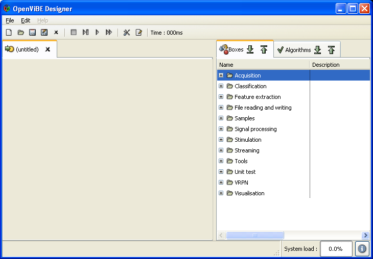
Designer main window upon startup
Step 2: Adding a box algorithm
Boxes are the building blocks of OpenViBE scenarios. A number boxes are included in your distribution of OpenViBE. They can be found uder the 'Boxes' tab on the right hand side of the Designer's main window.
Most scenarios need signal data to work on. A simple way to obtain such data consists in generating random signals using a Sinus Oscillator box. Let's expand the 'Samples' category. This should display a list of sample boxes, along with a short description. There should be a Sinus oscillator box among them. Let's drag and drop this item in the scenario edition window. The box should appear where the item was dropped.
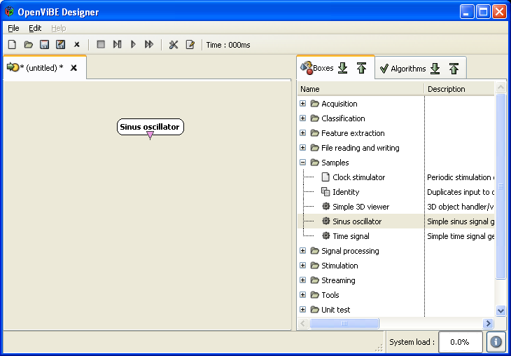
Drag and dropping the Sinus Oscillator samples box in the scenario edition area
Step 3: Connecting boxes
The Sinus Oscillator box generates random sinusoidal signals on a varying number of channels. We are going to display them on the screen using one of OpenViBE Designer visualisation boxes.
A simple way to do that is to add a Signal Display box to our scenario. This box displays signals for a varying number of channels in a popup window. It can be found under 'Visualisation', in the 'Basic' sub-category, along with other visualisation plugins. Drag and drop the Signal Display under the Sinus Oscillator box.
To forward data from the first box to the second, we must connect the Signal output of the Signal Oscillator to the Signal input of the Signal Display. Move the mouse cursor over box connectors (they lie on the box top and bottom edges and are represented as color-coded triangles). As the cursor is moved over a connector, a tooltip containing the connector name and type should appear. Once you have identified the right connectors, connect them by pressing the left mouse button on one connector, moving the mouse over the second connector and releasing the button. A link should now connect both connectors (to know more about the different types of connectors, see Connector Types).
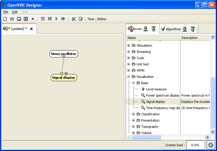
Linking box algorithms using their input and output connectors
Step 4: Saving a scenario
Before running a scenario, it is a safe practice to save it. There are two ways to do this :
- open the File menu situated in the top menubar and select the 'Save As' item, or
- click the 'Save As' icon, which can be found in the toolbar (right under the menubar) Enter a suitable name and click 'Save' to dump the scenario contents in a file.
Step 5 : Playing a scenario
Our scenario is now ready to be executed. Press the 'Play' button in the toolbar. A popup window should appear, displaying random sinusoidal signals.
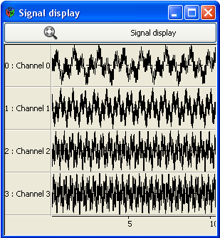
Signal Display box displaying sinusoidal signals
To stop the scenario, just press the 'Stop' button in the toolbar. The popup window should disappear, and you should be back to the scenario edition panel.
Congratulations, you have just completed your first tutorial!
To know more about OpenViBE Designer capabilities, including its window layout editor and how to customize scenario settings, proceed to the next tutorial : Tutorial 2.
| Back to top | Generated on Thu Jul 8 2010 16:31:34 for Documentation by  1.7.1 1.7.1 |